- Форум YourDevice
- Установка программатора AVR-USB (USBasp, AVR910, STK500) в windows vista, windows7(Seven)
- Установка программатора AVR-USB (USBasp, AVR910, STK500) в windows vista, windows7(Seven)
- AVR-Doper
- Features
- More Information
- Arduino, MK-90 и другие
- Страницы
- 21.07.2010
- AVR-Doper
- 3 комментария:
- AVRDoper
- Содержание
- AVR-Doper
- Возможности
- Подробная информация
- Производные работы
- Download
- Замечания к версиям
- Avr doper windows driver
Форум YourDevice
ЗАПИСНАЯ КНИЖКА ИНЖЕНЕРА == ((ПРОГРАММИСТ)&&(ЭЛЕКТРОНИК)&&(АСУТП)) -> TRUE
Установка программатора AVR-USB (USBasp, AVR910, STK500) в windows vista, windows7(Seven)

Установка программатора AVR-USB (USBasp, AVR910, STK500) в windows vista, windows7(Seven)
Сообщение admin » 18 янв 2012, 16:58
Если не получилось, то пишите на форуме, разберёмся. У меня всё работает  .
.
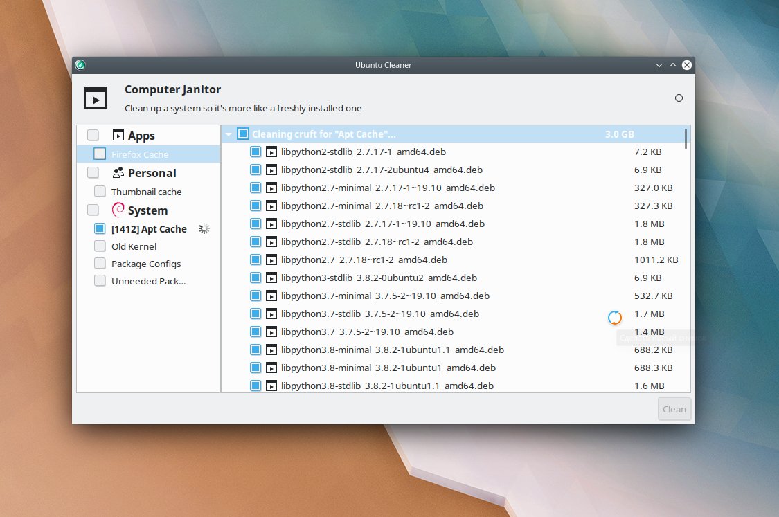
Установка программатора USBasp в windows vista/windows7(Seven) 32/64-бит.
Скачайте последнюю версию драйверов с http://www.fischl.de/usbasp/» target=»_blank . Подключите программатор к PC через USB, действуем как в ХР, выбрав соответствующий драйвер для Вашей системы.
Установка программатора AVR910 в windows vista/windows7(Seven) 32/64-бит.
Скачайте последнюю версию драйверов с http://prottoss.com/projects/AVR910.usb . rammer.htm» target=»_blank Подключите к программатор к PC через USB, описание по установке там же.
Видео по установке AVR910 usb на Windows7 64
Установка программатора STK500 (AVR-Doper) в windows vista/windows7(Seven) 32-бит.
Скачайте последнюю версию драйверов с http://www.obdev.at/products/vusb/avrdoper.html» target=»_blank .
Скачайте «avrcdc_inf.zip» от http://www.recursion.jp/avrcdc/lowbulk.html» target=»_blank
Подключите программатор к PC через USB. Операционная система найдет новое устройство. В диспетчере устройств укажите путь к inf-файлу, в зависимости от установленной на вашем компьютере операционной системы.
В архиве имеется папка » avrcdc_inf», в которой расположены директории для разных ОС.
Установка программатора STK500 (AVR-Doper) в windows vista/windows7(Seven) 64-бит.
Скачайте последнюю версию драйверов с http://www.obdev.at/products/vusb/avrdoper.html» target=»_blank .
Скачайте «avrcdc_inf.zip» от http://www.recursion.jp/avrcdc/lowbulk.html» target=»_blank
При установке на 64 битные платформы проблемы возникают из за цифровых подписей драйверов — в диспетчере устройств при выборе вкладки «Свойства» в окне надпись «Не удаётся проверить цифровую подпись драйверов. «.
Проблему можно решить несколькими способами.
Если пытались установить драйвера, то необходимо их удалить через диспетчер устройств.
Первый способ.
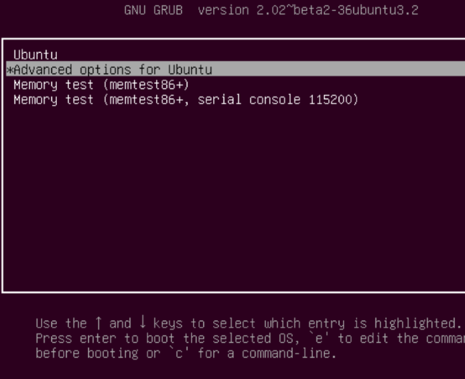
Отключить проверку цифровых подписей драйверов, нажав клавишу F8 во время начала загрузки системы и выбрав соответствующий режим загрузки.
Вторй способ.
Использовать программу «Driver Signature Enforcement Overrider».
AVR-Doper
Features
- HVSP allows using RESET pin for I/O, which is especially beneficial on 8 and 14 pin devices.
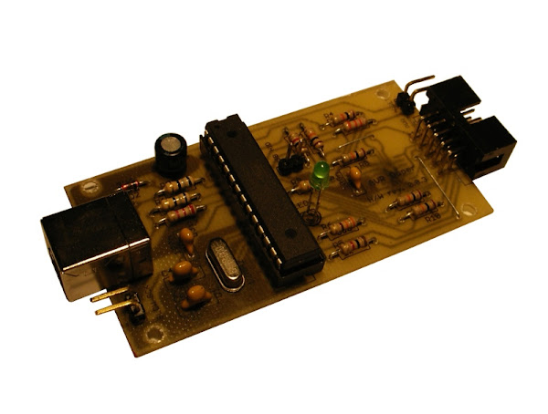
- Simple hardware which can be built on a single sided PCB. No special USB chips are needed.
- Compatible to Atmel’s STK500 with built-in USB to Serial converter.
- Adjustable ISP clock allows flashing of devices clocked at very low rate, e.g. 32 kHz.
- ISP clock can be lowered with a jumper (if the programmer software does not support setting the ISP clock).
- Second USB to Serial converter for processing debug output from the target.
- HVSP connector compatible with HVProg, another STK500 compatible programmer (see www.der-hammer.info/hvprog/index_en.htm).
- Uses USB power supply, no external supply required.
- Firmware can be compiled to run on metaboard hardware and USBasp hardware.
- Open Source (including firmware and schematics).
More Information
More information about the project and all the sources for hardware, software and firmware can be found in the download below.
Note: Implementing a USB CDC device with V-USB violates some aspects of USB 1.1. CDC-Mode may therefore fail or be unreliable on some operating systems or computer hardware. Please look at the compatibility list included in the AVR-CDC project or test a simplified prototype on breadboard with your computer if you want to use CDC mode.
We recommend that you use AVR-Doper in HID mode instead, which has no such problem. This mode is supported by avrdude. More information about interface modes and their relative advantages can be found in the project description.
Arduino, MK-90 и другие
Программирование Arduino, оживление микроэвм Электроника МК-90, аппаратный хакинг.
Страницы
21.07.2010
AVR-Doper
3 комментария:
Ардуина и сама себя неплохо программирует — зачем ей вообще внешний программатор нужен?)
Я когда свою собирал — запаял разъем Х3 и теперь им регулярно пользуюсь, как программатором)

а чем плох вот этот вариант?
http://arduino.cc/en/Tutorial/ArduinoISP
avrdude знает такой «программатор» (вот так я конектился к mega32
«avrdude -pm32 -P/dev/ttyUSB0 -carduino -b19200 -F -v»)

Согласен, варианты — рабочие, но на мое капризное imho — программатор должен быть отдельным девайсом. Так удобнее 😉
Про BitBang я уже писал, на тот момент оно требовало пропатченный avrdude. ArduinoISP я пробовал собирать в виде шилда, но что-то у меня получилось не так — работало через раз.
Ну и оба этих варианта не совместимы с AVRStudio.
AVRDoper
Эта страница является переводом оригинального текста: www.obdev.at/products/vusb/avrdoper.html
Содержание
AVR-Doper
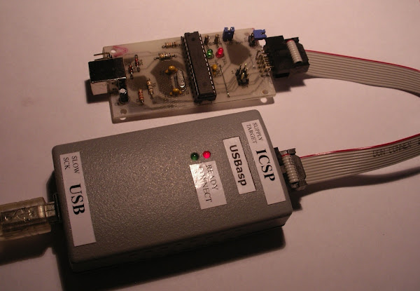
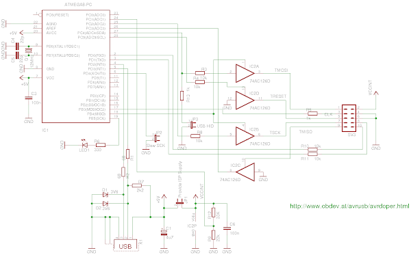
AVR-Doper — это STK500-совместимый внутрисхемный (In-System Programmer или ISP) программатор и высоковольтный последовательный программатор (High Voltage Serial Programmer или HVSP). Содержит встроенный USB-Serial адаптер для непосредственного подключения к шине USB.
Предупреждение: во всех версиях прошивки до 2007-08-07 включительно есть серьезная ошибка в режиме ISP! Пожалуйста, проведите апгрейд как минимум до 2007-12-01 (см. замечания к релизам ниже)!
Возможности
- Режим HVSP позволяет использовать в программируемом МК пин RESET в качестве обычного пина I/O, что особенно ценно в устройствах с 8 и 14 выводами;
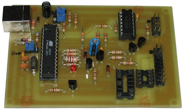
- Простая схема, которую можно собрать на односторонней печатной плате в домашних условиях. Не требуется отдельный USB-чип;
- Совместима с фирменным программатором STK500 от ATMEL со встроенным USB-to-Serial мостом;
- Возможность управлением тактовой частоты ISP, позволяющий прошивать устройства на небольшой скорости, от 32 kHz;
- Тактовая частота ISP может быть изменена джампером (если программирующий софт не поддерживает программую установку тактовой частоты);
- Для отладки можно использовать второй USB-to-Serial конвертер, подключив его к пинам отлаживаемого контроллера;
- Разъем HVSP совместим с HVProg — другим STK500-совместимым программатором (см www.der-hammer.info/hvprog/index_en.htm);
- Использует только питание от USB, других источников питания не требуется;
- Firmware может быть перекомпилировано для использования на железе Metaboard или USBasp.
- Open Source (включая firmware и схемы).
Подробная информация
Более подробная информация о проекте, включая файлы схемы и разводки, а также исходный код firmware могут быть скачаны по ссылкам ниже.
Замечание: Реализация CDC-устройства средствами V-USB противоречит некоторым разделам спецификации USB 1.1. Режим CDC может работать неверно или вовсе не заработать с некоторыми операционными системами и/или компьютерной аппаратуров. Пожалуйста, изучите список совместимого оборудования (информация включена в проект AVR-CDC) или протестируйте предварительно на макетной плате с вашим компьютером, в случае необходимости использования CDC-режима.
Мы рекомендуем использовать AVR-Doper в режиме HID, с которым проблем практически не возникает. Этот режим поддерживается avrdude. Более подробную информацию можно найти в документации к проекту.
Производные работы
Существует много возможностей усовершенствования AVR-Doper. Вот некоторые модификации схемы:
- www.rototron.info: упрощенная версия без HVSP;
- hobbyelektronik.org (на немецком): Более компактная плата для AVR-Doper;
- www.kreuzholen.de: в этой версии исключена часть HVSP, зато добавлена защита ESD и разработана PCB для готового корпуса, который можно купить. На этом сайте также предлагается альтернативный отладочный терминал, который использует для подключения встроенный порт AVR-Doper-а;
- www.z-v.si: альтернатива вышеописанной плате, но с односторонней PCB;
- оптоизолированный AVR-Doper: Версия без HVSP с опторазвязкой МК AVRDoper и программируемым МК;
- AVR tiny Doper SE: Немецкое руководство по созданию компактного программатора с полным набором возможностей.
Download
Для скачивания архива firmware и схем, выберите соответствующий линк ниже.
Замечания к версиям
Исправлен report ID для отладочной информации, передаваемой через HID. Этот интерфейс так пока и не использован, поскольку не написан драйвер для хоста.
Исправлен интерфейс определения схемы Metaboard/USBasp.
Для USBasp Timer 1 не конфигурируется.
Исправлена ошибка, внесенная в предыдущем релизе: LED pin не был сконфигурирован как выход для оригинальной схемы AVR-Doper.
Теперь присваивается серийный номер. Это должно помочь в ситуации с правильным закреплением виртуальных COM-портов за устройствами.
Улучшена скорость ISP.
Эта версия может быть скомпилирована под схемы Metaboard и USBasp.
Возвращен старый алгоритм вхождения в режим HVSP.
Добавлен .inf-файл для Windows Vista, требуется для работы в режиме CDC.
Исправлена серьезная ошибка в режиме ISP! Чтение фьюзов и аналогичные команды через avrdude могли приводить к непредсказуемым результатам, включая стриание чипа. Пожалуйста, обязательно обновитесь до этой версии!
Исправления в режиме HVSP для ATTiny24, 44 и 84 в схеме: пины 11, 12 и 13 в программируемом сокете должны быть подключены к GND.
HVSP протестирован с ATTiny11, 12, 13, 44 и 85.
Передача старших адресных бит в устройствах с более чем 64 kB флеш-памяти.
Утилита командной строки «avrdebug» принимает ввод с клавиатуры и может посылать его в target по последовательному интерфейсу
Утилита «avrdebug» теперь проверяет оба режима CDC и HID.
Подключены пины 2 и 3 в 8-пиновом сокете программирования. На некоторых 8-пиновых устройствах эти пины поменяны местами.
Добавлен патч avrdude для поддержки HID-режима.
Обновлено Readme об использовании режима HID в avrdude.
Добавлены макросы для возможности использования ATMega88 вместо ATMega8.
Игнорирование параметра synchLoops в режиме ISP, поскольку avrdude иногда посылает 0.
Изменена скорость ISP по умолчанию на 2 (было — полная скорость).
Avr doper windows driver
This is the README file for AVR-Doper.
AVR-Doper is an STK500 compatible In-System Programmer (ISP) and High Voltage Serial Programmer (HVSP). It comes with a built-in USB to Serial adaptor to connect directly to USB.
- HVSP allows using RESET pin for I/O, which is especially beneficial on 8 and 14 pin devices.
- Simple hardware which can be built on a single sided PCB. No special USB chips are needed.
- Compatible to Atmel’s STK500 with built-in USB to Serial converter.
- Adjustable ISP clock allows flashing of devices clocked at very low rate, e.g. 32 kHz.
- ISP clock can be lowered with a jumper (if the programmer software does not support setting the ISP clock).
- Second USB to Serial converter for processing debug output from the target.
- HVSP connector compatible to HVProg, another STK500 compatible programmer (see http://www.der-hammer.info/hvprog/index_en.htm).
- Open Source (including firmware and schematics).
- Uses USB power supply, no external supply required.
- Can be used as alternative firmware on metaboard based programmer, see http://www.obdev.at/goto?t=metaboard-prog
- Can be used as alternative firmware for Thomas Fischl’s USBasp hardware, see http://www.fischl.de/usbasp/
AVR-Doper can be used in two modes: (1) With a built-in USB to serial converter and (2) with a special communication protocol based on the USB HID standard.
The built-in USB to serial converter does not work with all PC hardware and all operating systems. We therefore STRONGLY recommend that you use AVR-Doper in HID mode. This mode uses a different communication protocol on USB and requires special programming software. It is supported by the Open Source command line tool «avrdude» since version 5.3. Older versions can be patched, see the file Readme.txt in the subdirectory «avrdude» for more information.
Readme.txt . The file you are currently reading. firmware . Source code of the controller firmware. firmware/usbdrv . USB driver — See Readme.txt in this directory for info avrdebug . Source code for the optional debug-reader command line tool. The directory also contains a windows executable of avrdebug which requires libusb-win32 (a HID based Windows version is now available, too) and a python serial driver for AVR-Doper’s debug interface. circuit . Circuit diagrams in PDF and EAGLE 4 format. A free version of EAGLE is available for Linux, Mac OS X and Windows from http://www.cadsoft.de/. License.txt . Public license (GPL2) for all contents of this project. Changelog.txt . Logfile documenting changes in soft-, firm- and hardware. avrdoper.inf . Driver description file for Windows. avrdoper-vista.inf Driver description file for Windows Vista. avrdude . Directory containing instructions how to patch avrdude to to work with AVR-Doper’s HID mode. Version 5.3 and newer don’t need to be patched.
AVR-Doper can be run in two modes, see the warning section above. We recommend that you use it in HID mode with «avrdude» as the programming tool. In order to set the hardware into this mode, set jumper «USB HID». Use «avrdoper» as the hardware port for avrdude, e.g.:
HID-Mode does not work with Atmel’s AVR-Studio 4 because Atmel does not implement our special HID-based protocol.
This mode is strongly discouraged, see the warning section above. If you still decide to use it (e.g. because it works well with your components), remove the «USB HID» jumper from the circuit. AVR-Doper will then present itself as an USB modem to the operating system. This modem interface uses the same communication protocol as the original serial STK500 board described in Atmel’s application note AVR068. In this mode, AVR-Doper can be used with any software which supports the STK500 in firmware revision 2, including Atmel’s AVR-Studio 4 and the Open Source command line tool avrdude.
** WINDOWS ** To use AVR-Doper in this mode on Windows, you must first install drivers for its CDC-ACM class USB to Serial converter. Luckily, these drivers are part of Windows. To activate these drivers for AVR-Doper, connect the device. Windows will bring up a «new hardware» assistant. Proceed as follows:
- Do not connect to Windows Update to search for a driver.
- Insert a medium with the «avrdoper.inf» file or have the file available somewhere on your computer.
- If the assistant can’t find a medium with avrdoper.inf, it will ask for a folder where this file resides. Answer this question.
- Choose «simple installation». Windows will warn you that the software, which shall be installed, has not passed the «Windows Logo» test. This is interesting, since the drivers are provided by Microsoft themselves. Continue the installation in spite of the aggressive warnings.
When the assistant has finished, a new COM port (it was COM5 on our computer) is available. Start AVR Studio 4 (available for Free from www.atmel.com) and test the programmer.
Since Windows Vista, the operating system enforces the USB standard and forbids bulk endpoints on low speed devices. Osamu Tamura has a driver which solves this problem by mapping the bulk endpoints to interrupt endpoints. See http://www.obdev.at/goto.php?t=lowbulk for details.
** Mac OS X ** On Mac OS X, just connect the device. It will be recognized by the operating system and be accessible as /dev/cu.usbmodem. where «. » stands for a combination of digits and letters. Test it with avrdude 5, e.g.:
** Linux ** Just connect the device. It will be available as /dev/ttyACM0. Test with avrdude as above.
AVR-Doper’s hardware should be easy to build. All components are easy to obtain, except maybe the 1 mH inductor. You can replace it with any inductor in the range 330 uH to 10 mH. Be SURE TO CHECK the 12 V at the cathode of D3 before you use HVSP. If the voltage exceeds the range 11 V — 13 V, you can either tune the voltage divider R5/R18 or change the reference constant in the firmware (see vreg.c, constant «VREG_REF»).
The 3.6 V zener diodes D1 and D2 should be low power types. If you can’t get hold of low power zener diodes, you may have to use 3.9 V types due to the round edge of the cut-off voltage found in low voltage zener diodes.
If you don’t want the HVSP feature, you can omit many of the analog components: L1, T1 — T5, D3, D4, R4, R5, R12 — R16, R18, C2, C7, the programming sockets IC3 and IC4 and the 20 pin HVSP connector.
AVR-Doper ships with a ready-made hex-file containing the firmware. Flash it with whatever programmer you get hold of. If you don’t have a programmer yet, have a look at the simple «parallel port» programming adapters available on the internet. Please note that you must also change the fuse bytes of the ATMega8. See the main Makefile (search for «fuse») for the hexadecimal fuse values and for the options we require.
If you want to compile from the sources, you need avr-gcc, the GNU compiler for the AVR platform. On Windows, download WinAVR, an integrated development environment including avr-gcc and all associated tools (http://winavr.sourceforge.net/). For the Mac, we recommend AVR MacPack available from http://www.obdev.at/avrmacpack/. On other platforms you need to compile avr-gcc and avr-libc from the sources. Please read the instructions at http://www.nongnu.org/avr-libc/user-manual/install_tools.html for how to install all this stuff.
Once you have avr-gcc installed, just type «make» in the «firmware» directory to build the code.
AVR-Doper comes with only one software tool and even this is optional: the debug logger «avrdebug». This tool requires libusb (on Unix) or libusb-win32 (on Windows). You may have to edit the Makefile to compile it on Windows.
«avrdebug» takes no command line parameters. It simply searches for AVR-Doper on the USB, attaches to the device and logs all debug data received at the programmer’s RxD line. Each line of ASCII input is prefixed with a timestamp.
Firmware Update AVR-Doper has no ISP socket to flash AVR-Doper’s own firmware. You must therefore move the ATMega8 to an external programmer for initial firmware flashing. This can be tedious if you work on AVR-Doper’s firmware. We can highly recommend Thomas Fischl’s boot loader in this case. The new firmware is simply flashed over AVR-Doper’s own USB port. See http://www.fischl.de/avrusbboot/ for details.
Tuning Code Size The AVR-Doper firmware fits easily into an ATMega8, but not together with a boot loader. If you want to use a boot loader, you must disable at least one feature (such as e.g. the HID interface). This can be done in the header file hardware.h.
External Programming Socket The ISP interface can supply an external stand-alone programming socket with power and processor clock. You must set jumper JP1 to connect the ISP power to the programmer’s power supply. The processor clock is available at ISP pin 3, which was otherwise used for a programming indicator LED.
Debugging Target Firmware AVR-Doper has an additional USB to Serial converter which reads serial data from the ISP connector’s pin 10. This pin is normally ground. If you connect your target’s TxD (via a resistor to protect it from short circuit) to this pin, you can read the debug output with the «avrdebug» command line tool. The debug baud rate is 19200 bps (fixed).
Setting ISP clock AVR-Doper uses a moderate ISP clock (
100 kHz) after power-up. You can change the ISP clock in AVR Studio’s «Board» settings or with the «-B» option in avrdude (since version 5.1). If your programming software does not support setting the ISP clock, set jumper JP2 to reduce the ISP clock to
7 kHz, suitable for CPU clock rates down to 32 kHz. Note that the «-B» option of avrdude is not exactly in microseconds. For serial clocks of
300 kHz / 100 kHz / 50 kHz use values 1.1, 2 and 3. Higher «-B» values give a ISP clock of